
Wherein I build a smart home out of dissected christmas lights.
 These lights, in particular.
Introduction
On account of the pandemic, I found myself with a lot of free time over the winter break. Although I was disheartened that I couldn’t visit my friends and family en masse, I was rather excited at the prospect of having time to get personal projects done. Usually I’m either busy with school or trying to cram in family time, so large spans of unfilled time are quite rare.
As the owner of a set of Philips Hue lights (and a set that are old enough to have stopped receiving updates), I decided to finally get around to setting up HomeAssistant, an open-source home automation controller. It aims to unify IoT devices by allowing you to control everything at one interface, and also allows you to set up a smart home that stinks a little less of corporate spyware.
Setting up HomeAssistant
HomeAssistant is easiest to set up on a Raspberry Pi, but performance can be subpar on the older models (thanks, Python). It’s also possible to install HomeAssistant on any Debian system, but neither of those methods were quite right for me. I do have an old PC I use as a server, but installing only HomeAssistant would be wasteful of those computational resources.
After a bit of digging, I discovered Proxmox Virtual Environment - an open-source, debian based server OS designed for virtualization. It provides a local web interface that makes controlling multiple virtual machines simple. As a result, I am able to concurrently run both HomeAssistant and a general-purpose development server on a single machine.
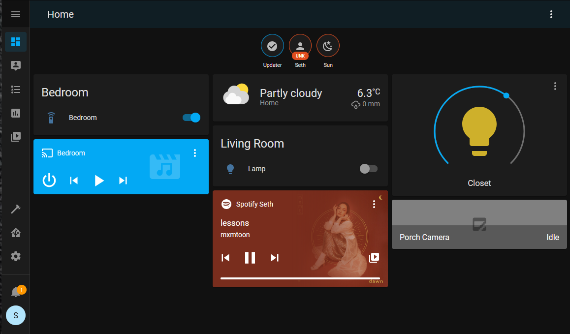 A screenshot of the HomeAssistant dashboard.
Once set up, HomeAssistant really starts to shine! The setup process is a breeze, and just using local network discovery, it was able to connect with far more than I expected. Spotify, HomeKit, Philips Hue, and Apple TV were the only things I configured during the initial setup, and it only took a few minutes.
Custom Lighting with MySensors and FastLED
The time that I first got this working was right around christmas, and as such, I had bought a reel of christmas lights a week or so prior. As I played with the modes, I realized that the lights were following patterns that would only be possible if they were individually addressable. I was somewhat surprised, because they’re quite cheap, but began digging around out of curiosity.
As I examined the electronics, I quickly developed a hunch that the christmas lights were using WS2812 LEDs. The WS2812 is a cheap surface-mount RGB LED which is popular in the hobby electronics world due to their simple addressing scheme - instead of having to cleverly multiplex hundreds of LEDs to a hobby microcontroller, the WS2812s can be connected in a cascade, allowing the designer to only use one microcontroller pin for communication. My christmas lights only had three wires connecting the LEDs, which I suspected were ground, a positive voltage rail, and a data line (which is consistent with the WS2812).
Because these LEDs are so popular, there is a vast amount of driver code and documentation available online. Although I was still somewhat worried I was about to destroy the strip, I severed the christmas lights from their controller, soldered them to a three-pin header, and connected them to an arduino running some example code I’d found online.
And they worked!
A demo of the christmas lights running custom firmware!
At this point, I started to realize how useful they could be when connected to my HomeAssistant sever. My apartment lighting is less than ideal in several places, especially my storage closet, which has no light at all (despite having a light switch).
Although it took a fair bit of research to solidify my plan for this project, I finally settled on an execution plan. I’d already worked out the HomeAssistant side of things, but how was I going to connect my microcontroller to that system?
Ultimately, I found an Arduino library called MySensors, which aims to make developing smart devices cheap and unifiable. However, there are a few steps along the way to getting started.
Although it would seem obvious to use WiFi for communicating with your smart home devices, it can often be too power-hungry. Additionally, WiFi hardware can be a little more expensive than lower frequency radios, which makes it a bit of a hard sell for cheap, battery-powered smart home devices. As a way to mitigate this, MySensors recommends the use of a gateway, which is a circuit that connects a low-power mesh network of smart devices to your home internet.
I put together a gateway using an ESP32 I had on hand, and 3D printed a case for it. Then, I was finally able to get to the meat of this project - controlling the lights!
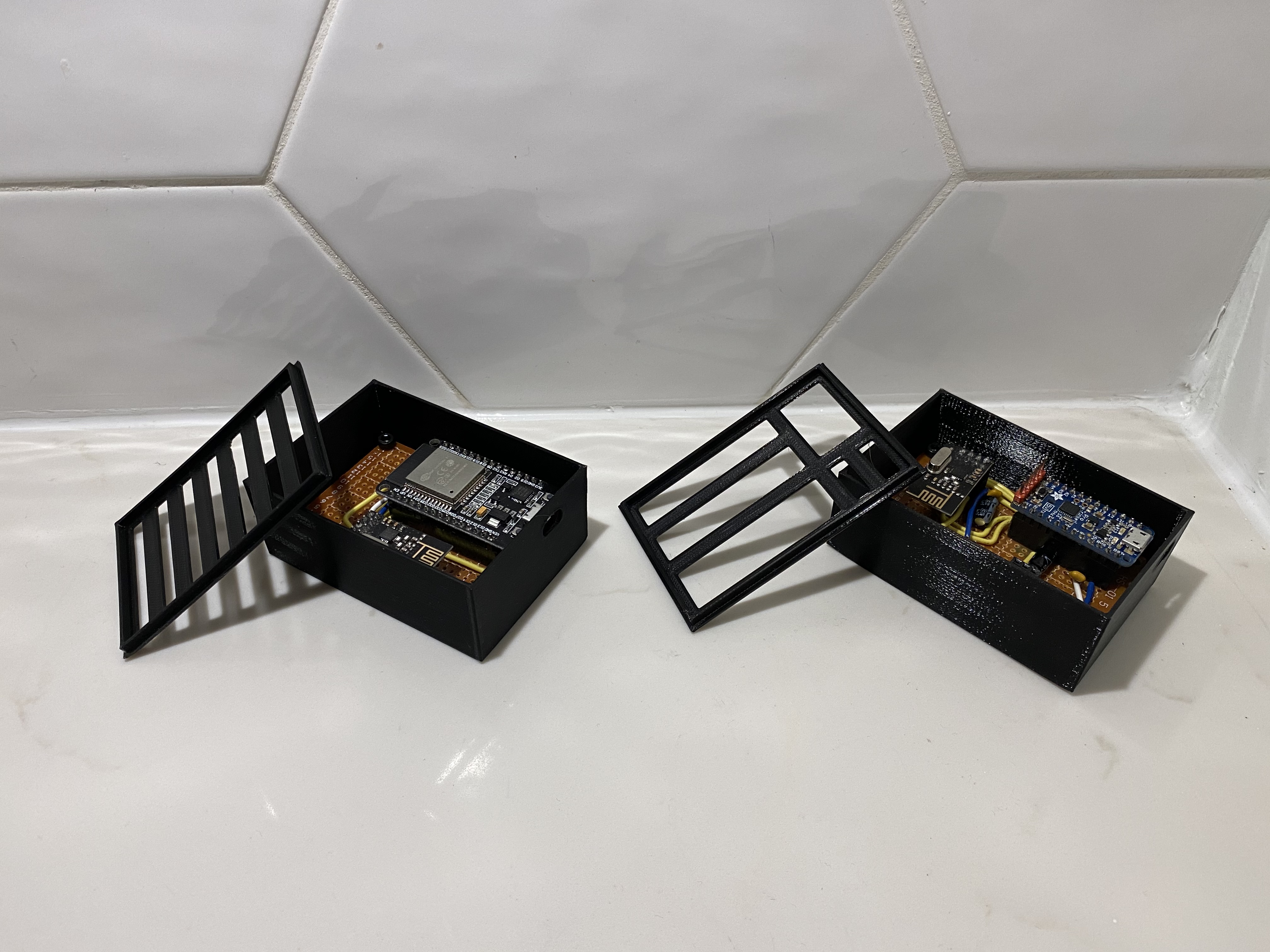 The gateway (left) and the light controller (right).
The device that drives my LEDs has a few requirements that I needed to tinker with. Namely:
- The radio needs 3v3 The microcontroller needs 5v The LEDs draw 2 amps (so
- care must be taken to route power outside of the delicate MCU traces)
The voltage requirements wouldn’t be a problem usually, but I didn’t have any suitable linear regulators on hand! I ended up employing an emitter-follower transistor circuit as a functional approximation.
Firmware
Having built the hardware, I got to work adapting two example programs (one from MySensors, and the other from FastLED, the WS2812 driver) together. Although I was able to have full RGB control of each LED, I honestly find RGB lights a bit kitschy and impractical - am I ever going to want to turn my closet blue? As a result, I initially programmed the whole strip to be a dimmable warm white.
Once I’d finished assembling and programming my hardware, I hung the light strip on the ceiling of my closet. I also added a transition animation for adjusting their brightness, which highlights their individual controllability in lieu of fun rainbow effects.
Conclusion & Final Tweaks
The system works really well, and I thought I was done until a few days ago. The color I chose was a little too dim even at full brightness, and I wanted to make lower brightnesses fade to red in order to spare myself some eye strain. So, the final tweak I added was a color changing effect - at minimum brightness, they’re a dim, saturated red. As the brightness increases, the hue fades to yellow, and saturation yields to a bright white. As the color and saturation are pure functions of the brightness, l get the benefit of RGB lighting, without having to fiddle with a color picker!
Media
 The lights showing their animation, and the color at different brightnesses.
The gateway (left) and the light controller (right). 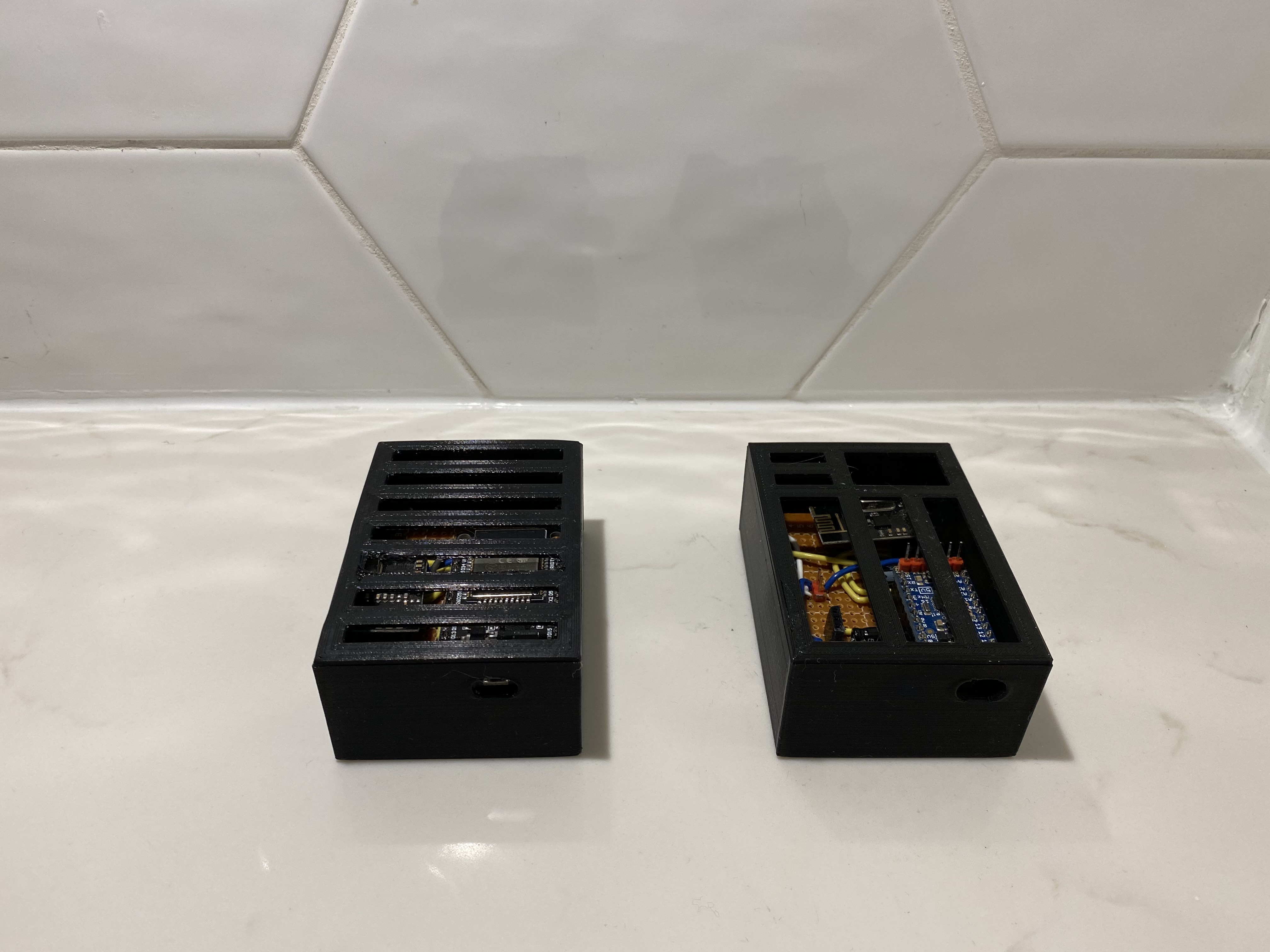 The same duo as above, but with their lids on. The design of the controller’s lid had to account for cable routing through the top plate. Using the USB port to power the LEDs would blow out the microcontroller’s voltage regulator.
Further plans
I plan to design a PCB which will make building copies of this light controller much easier - this is far by the only spot with bad lighting in my apartment, and I’d love to have some more control.